
MEP BIM Modeling for Data Centers: Precision Engineering for Mission-Critical Facilities
In a data center, a single clash between a cooling pipe and a cable tray can mean hours of downtime and millions in losses. Here’s how MEP BIM modeling removes that risk before a single pipe is installed.
Table of Contents
Data centers are among the most mechanically and electrically dense buildings ever constructed. Every square meter is packed with chilled water pipework, busbars, cable trays, CRAC/CRAH units, fire suppression lines, and redundant power paths — all of which have to fit together with zero tolerance for error. MEP BIM modeling is the discipline that makes that possible.

What Is MEP BIM Modeling for Data Centers?
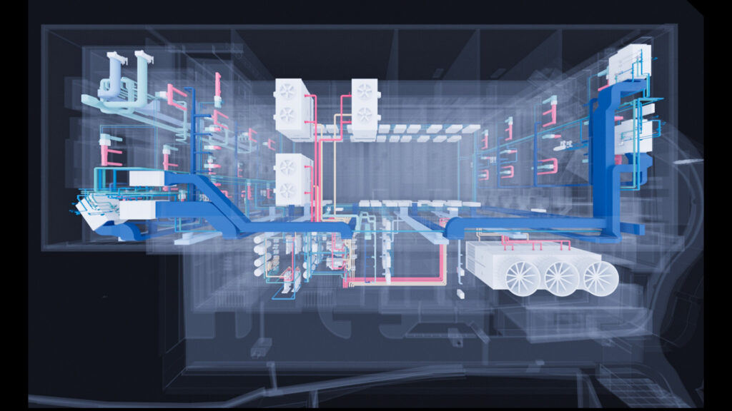
MEP BIM modeling is the process of building coordinated 3D digital models of a data center’s mechanical, electrical and plumbing (public health) systems inside a shared Building Information Model — typically in Autodesk Revit. Instead of designing cooling, power and drainage systems on separate 2D drawings, every duct, pipe, cable tray, busbar, and piece of equipment is modeled as an intelligent 3D object, positioned exactly where it will be installed and linked to real engineering data.
For a typical office building, MEP BIM is a matter of convenience. For a data center, it’s a matter of uptime. Mechanical and electrical systems in a mission-critical facility are not a background service — they are the building. Cooling capacity, redundant power paths (N+1, 2N), and containment systems define whether the facility can hold its SLA, and MEP BIM is how design teams prove, on screen, that every system fits and functions before construction begins.
Key definition: MEP BIM modeling for data centers is not just 3D drafting — it’s coordinated engineering. The model carries real specifications (flow rates, cable sizes, equipment tags, clearances) that mechanical, electrical and public health disciplines are checked against, together, in one federated environment.
Why Data Centers Demand a Different Level of MEP Precision
Data centers differ from almost any other building type in three ways that directly affect MEP BIM scope:
- System density. A single white space or plant room can carry dozens of parallel service runs — chilled water, condenser water, busbar trunking, containment ductwork, fire suppression, leak detection — all routed through the same limited ceiling and raised-floor voids.
- Redundancy requirements. Tier III and Tier IV facilities require concurrently maintainable or fault-tolerant MEP systems, meaning duplicate routes for power and cooling that all have to be modeled and coordinated independently.
- Zero tolerance for rework. Once a data hall is live, MEP changes are disruptive and expensive. Clashes have to be resolved in the model — long before steel is cut or pipe is welded.
This is why data center clients increasingly specify LOD 350–400 MEP BIM models with full clash detection as a contractual deliverable, not an optional extra.
The MEP BIM Workflow for Data Center Projects
A well-run MEP BIM process for a data center follows a consistent sequence, whether the project is a new-build hyperscale campus or a retrofit inside an existing facility.
Requirements & BIM Execution Plan (BEP)
The team agrees on LOD, software (typically Revit, Navisworks, and BIM 360/ACC), naming conventions, and coordination cadence with the client and other disciplines before modeling starts.
Mechanical & Electrical Modeling
CRAC/CRAH units, chillers, chilled water and condenser piping, ductwork, generators, UPS systems, busbars, cable trays, and switchgear are modeled from engineering drawings, equipment schedules, and manufacturer data.
Public Health & Fire Protection Modeling
Drainage, leak detection piping, and fire suppression systems (often gas-based clean agent systems for white space) are added to the same federated model.
Clash Detection & Coordination
All MEP disciplines, structure, and architecture are combined in Navisworks for interference checking. Clashes between ductwork, cable trays, structural steel, and raised-floor supports are logged and resolved before issue.
Shop Drawings & Asset Data Handover
Once coordinated, the model is used to generate installation-ready shop drawings and, at LOD 400, spool and prefabrication drawings — plus asset data for the client’s CAFM/CMMS system.
Core MEP Systems Modeled in Data Center BIM
Mechanical (Cooling & Airflow)
Chilled water plant, CRAC/CRAH units, in-row cooling, hot/cold aisle containment ductwork, and — increasingly — liquid cooling loops for high-density racks. Accurate mechanical BIM ensures airflow paths, pipe insulation clearances, and equipment service zones are respected.
Electrical (Power Distribution)
Busbar trunking, cable tray routes, switchgear rooms, UPS and battery rooms, generators, and standby power paths. In a 2N architecture, the model has to keep the two redundant paths physically and visually separated — something only a coordinated 3D model can verify reliably.
Public Health (Plumbing & Drainage)
Leak detection piping beneath raised floors, condensate drainage from cooling units, and make-up water lines for evaporative cooling systems — all modeled to avoid routing over sensitive electrical equipment.
Fire Protection
Clean agent gas suppression, pre-action sprinkler systems, and VESDA (early smoke detection) piping — coordinated tightly with cable containment and cooling ductwork above the data hall ceiling.
Levels of Development (LOD) for Data Center MEP
As with any BIM deliverable, the target Level of Development defines how much detail the MEP model carries — and it should be agreed before pricing or scheduling the work.
| LOD | What’s Modeled | Typical Use in Data Centers |
|---|---|---|
| LOD 200 | Generic MEP equipment and routing, approximate sizing | Concept design, capacity planning |
| LOD 300 | Accurate sizing, routing, and equipment placement | Design development, permit submission |
| LOD 350 | Full coordination geometry — connections, supports, clearances | MEP coordination, clash detection |
| LOD 400 | Fabrication-level detail, manufacturer-specific families, spool drawings | Prefabrication, installation, shop drawings |
Most of our data center engagements are scoped at LOD 350–400, since coordination and shop-drawing production are exactly where MEP BIM delivers the most value on mission-critical projects.
Key Benefits for Owners, Contractors & MEP Engineers
🧊
Guaranteed Cooling Capacity
Modeled airflow paths and clearances confirm cooling systems will perform as designed before installation.
⚡
Verified Redundancy
N+1 and 2N power/cooling paths are checked in 3D to confirm true physical separation, not just paper compliance.
🔍
Clash-Free Installation
Interferences between ductwork, cable tray, pipework and structure are caught in the model — not on-site with the trades already mobilized.
⏱️
Faster Time to Commissioning
Coordinated shop drawings speed up prefabrication and installation, shortening the path to go-live.
💰
Lower Rework Costs
Resolving conflicts digitally avoids the cost of cutting, re-routing or re-welding installed MEP systems.
📂
FM-Ready Asset Data
The delivered model carries equipment tags and maintenance data that feed directly into the facility’s CMMS/CAFM platform.
Our Data Center Projects
Trident BIM has delivered MEP BIM modeling and coordination for mission-critical facilities across Europe and the Middle East. Below are three representative projects from our portfolio.
Data Center in Western Europe
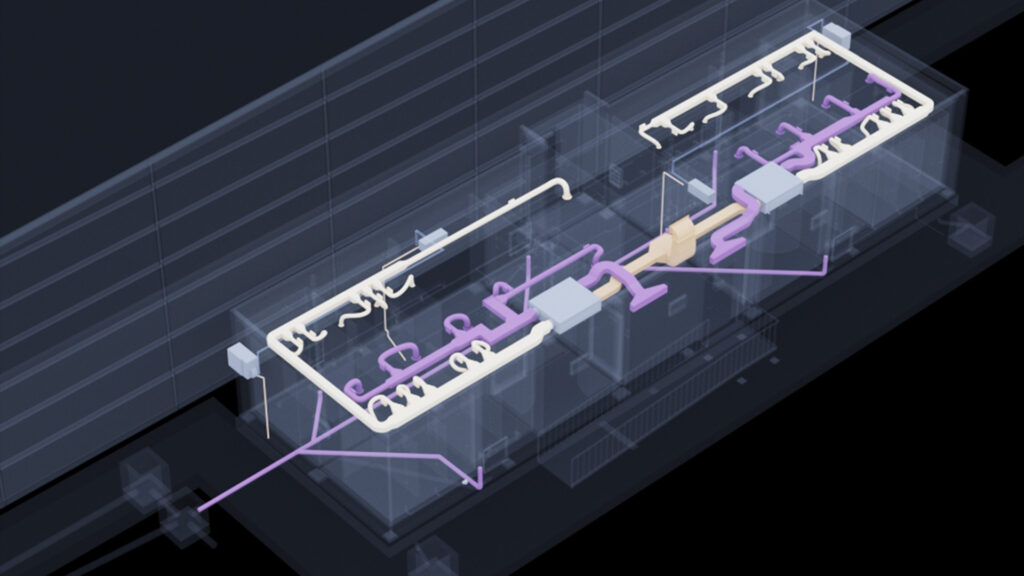
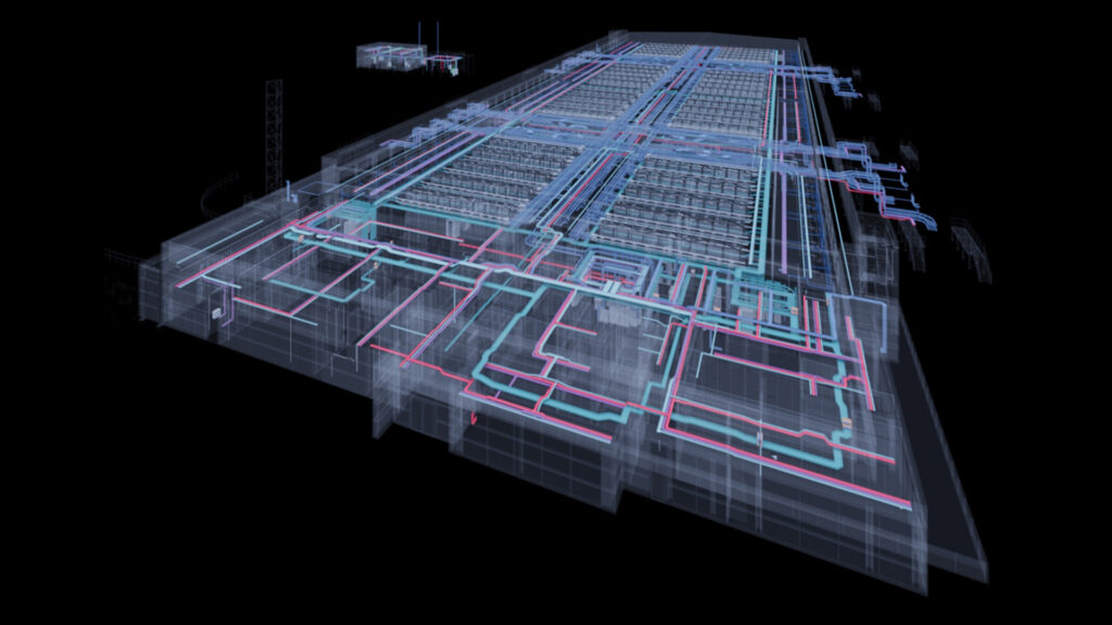
Working as BIM outstaff for one of the region’s leading mission-critical delivery teams, Trident BIM supported this data storage facility through many rounds of design amendments and iterations — a routine reality on mission-critical projects, where changes to IT load or redundancy strategy ripple through every MEP system.
Scope covered mechanical and electrical services modeling and coordination, shop drawing production, asset management input, and public health BIM, keeping the federated model current through every design revision.
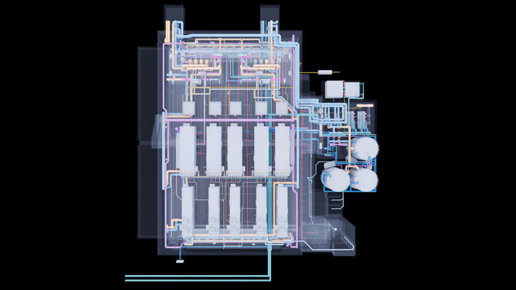
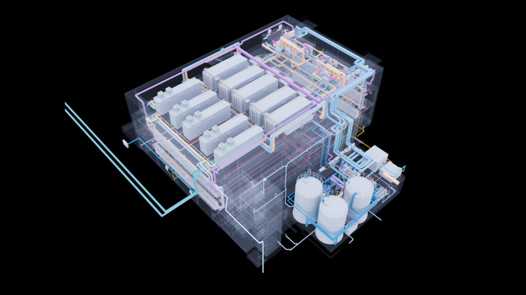
Data Center in Northern Europe
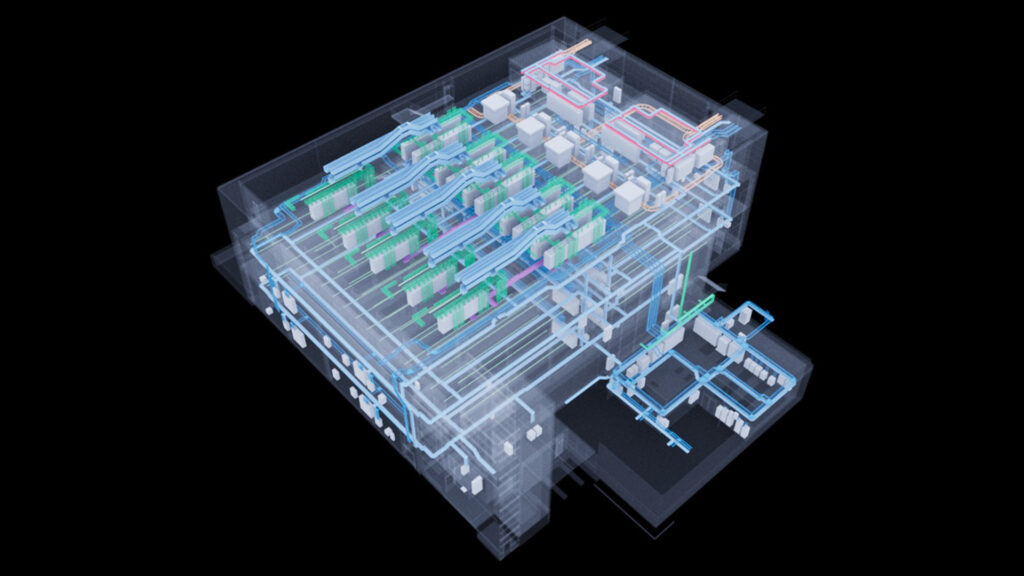
In collaboration with one of Europe’s leading mission-critical contractors, Trident BIM modeled and coordinated an exceptionally MEP-dense data center — bringing complex cooling and power distribution technologies to life in a fully coordinated 3D environment ready for installation.
The scope included mechanical and electrical services modeling and coordination, shop drawing production, asset management input, and public health BIM, issued directly for site installation.
Data Center in Israel
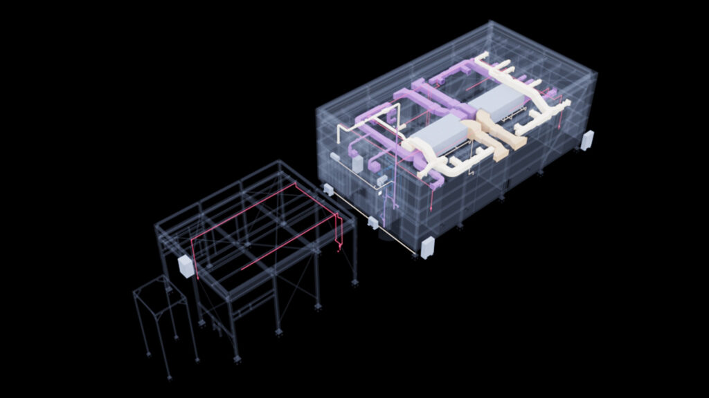
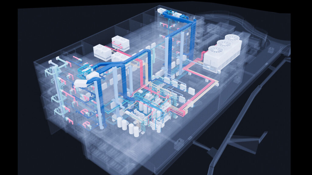
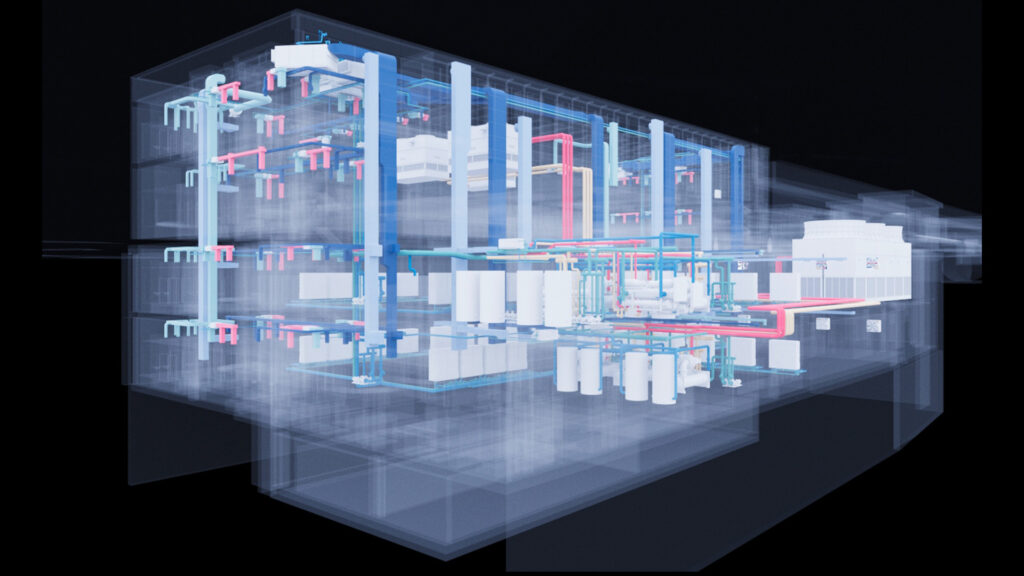
Though the scope was limited to mechanical services modeling and coordination, this project gave the Trident BIM team valuable hands-on experience with the exacting standards of TIER 4 data center construction, where fault-tolerant redundancy leaves no room for coordination error.
Common Challenges — and How BIM Solves Them
Compressed schedules
Data center clients often need capacity online fast. Coordinated MEP BIM shortens the path from design to installation by resolving clashes digitally, before crews are on site.
Frequent design changes
IT load and redundancy strategy can shift mid-project. A federated BIM model lets MEP teams absorb those changes and re-check coordination quickly, instead of re-drafting from scratch.
Multiple contractors, one ceiling void
Mechanical, electrical, public health and fire protection trades are often different subcontractors working in the same tight overhead space. A shared, coordinated model is the only reliable way to keep their work from colliding.
FAQ
Frequently asked questions
What LOD does a data center MEP BIM model typically need?
Most data center coordination and installation work is scoped at LOD 350, with LOD 400 used where prefabrication of pipe spools or duct sections is planned. Design-stage models may start at LOD 200–300 before being developed further.
How long does MEP BIM modeling take for a data center?
Timelines depend on facility size, redundancy tier, and required LOD. A single data hall coordination package can take a few weeks; a full campus with multiple mechanical and electrical rooms at LOD 400 can take several months. We provide a scoped estimate before work begins.
Can you work as an extension of our in-house BIM team?
Yes. On several of our data center projects we’ve worked in a BIM outstaff role, embedded directly in the client’s coordination process and design revision cycle, rather than delivering a single fixed handover.
Do you provide clash detection as part of MEP BIM modeling?
Yes. Clash detection and coordination across mechanical, electrical, public health, structural and architectural models is a core part of our data center BIM Coordination & Clash Detection service.
Can you model MEP systems from an existing (as-built) data center?
Yes. For retrofits and upgrades inside operating facilities, we combine Scan to BIM with MEP modeling, capturing existing conditions with laser scanning before designing new systems around verified as-built geometry.